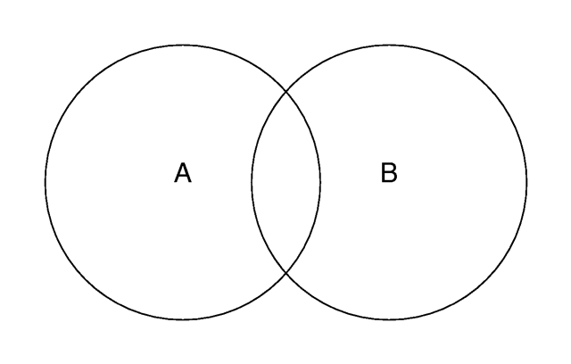
Two overlapping objects.
CSG shapes may be used anywhere a standard shape can be used, even inside other CSG shapes. They can be translated, rotated or scaled in the same way as any other shape. The shapes making up the CSG shape may be individually translated, rotated and scaled as well.
Given any point in space you can say it's either inside or outside any particular primitive object. Well, it could be exactly on the surface but this case is rather hard to determine due to numerical problems.
Even planes have an inside and an outside. By definition, the surface normal of the plane points towards the outside of the plane. You should note that triangles and triangle-based shapes cannot be used as solid objects in CSG since they have no well defined inside and outside.
CSG uses the concepts of inside and outside to combine shapes together as explained in the following sections.
Imagine you have to objects that partially overlap like shown in the figure below. Four different areas of points can be distinguished: points that are neither in object A nor in object B, points that are in object A but not in object B, points that are not in object A but in object B and last not least points that are in object A and object B.
Keeping this in mind it will be quite easy to understand how the CSG operations work.
Note that the difference operation is performed by intersecting the first object with the negation of the second object.
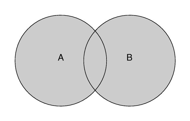
Unions are simply glue used to bind two or more shapes into a single entity that can be manipulated as a single object. The image above shows the union of A and B. The new object created by the union operation can be scaled, translated and rotated as a single shape. The entire union can share a single texture but each object contained in the union may also have its own texture, which will override any matching texture statements in the parent object.
You should be aware that the surfaces inside the union will not be removed. As you can see from the figure this may be a problem for transparent unions. If you want those surfaces to be removed you'll have to use the merge operations explained in a later section.
The following union will contain a box and a sphere.
Earlier versions of POV-Ray placed restrictions on unions so you often had to combine objects with composite statements. Those earlier restrictions have been lifted so composite is no longer needed. Composite is still supported for backwards compatibility but it is recommended that union is now used in it's place since future support for the composite keyword is not guaranteed.
For example:
The results is a subtraction of the 2nd shape from the first shape as shown in the figure below.
For example:
The merge operations can be used to avoid this problem. It works just like union but it eliminates the inner surfaces like shown in the figure below.
The different types of light sources and the optional modifiers are described in the following sections.
The other keywords will be explained later.
The spotlight is identified by the spotlight keyword. It is located at LOCATION and points at POINT_AT. The following illustration will be helpful in understanding how these values relate to each other.
The spotlight's other parameters are radius, falloff and tightness.
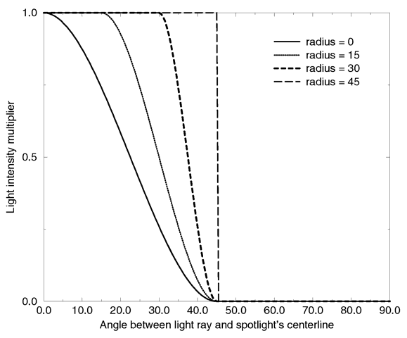
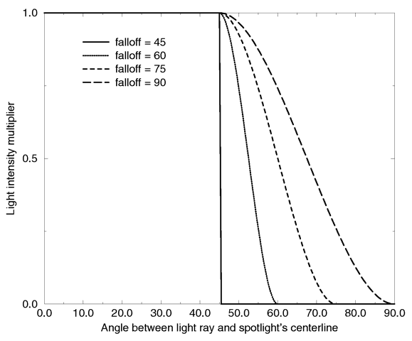
Think of a spotlight as two nested cones as shown in the figure. The inner cone is specified by the radius parameter and is fully lit. The outer cone is the falloff cone beyond which there is no light. The values for these two parameters are half the opening angles of the corresponding cones, both angles have to be smaller than 90 degrees. The light smoothly falls off between the radius and the falloff angle like shown in the figures below (as long as the radius angle is not negative).
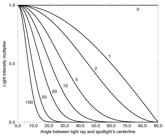
The tightness value specifies how quickly the light dims, or falls off, from the spotlight's center line to the falloff cone (full darkness outside). The default value for tightness is 10. Lower tightness values will make the spotlight brighter, making the spot wider and the edges sharper. Higher values will dim the spotlight, making the spot tighter and the edges softer. Values from 1 to 100 are acceptable.
You should note from the figures that the radius and falloff angles interact with the tightness parameter. Only negative radius angles will give the tightness value full control over the spotlight's appearance as you can see from the figure below. In that case the falloff angle has no effect and the lit area is only determined by the tightness parameter.
Spotlights may be used anyplace that a normal light source is used. Like any light sources, they are invisible. They are treated as shapes and may be included in CSG shapes. They may also be used in conjunction with area lights.
Section 7.5.5.5
Intersection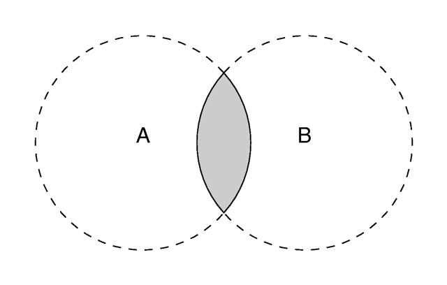
The intersection of two objects.
Section 7.5.5.6
Difference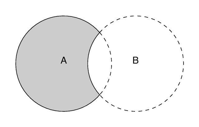
The difference between two objects.
Section 7.5.5.7
Merge
Merge removes inner surfaces.
Section 7.5.6
Light Sources
Section 7.5.6.1
Point Lights
Section 7.5.6.2
Spotlights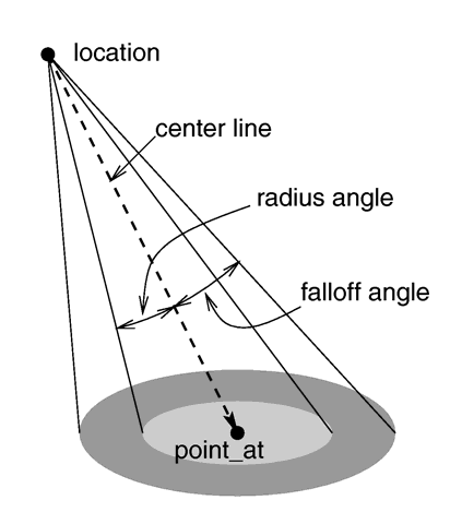
The geometry of a spotlight.
Intensity multiplier curve with a fixed falloff angle of 45 degrees.
Intensity multiplier curve with a fixed radius angle of 45 degrees.

Intensity multiplier curve with fixed angle and falloff angles of 30 and 60 degrees respectively and different tightness values.
Intensity multiplier curve with a negative radius angle and different tightness values.
Table Of Contents