Section 4.8.5.3
The Glowing Halo

We have mentioned the glowing halo in the section about the emitting halo as one way to avoid the color mixing that is happening with emitting halos.

The glowing halo is very similar to the emitting halo except that it also absorbs light. We can view it as a combination of the emitting and the attenuating halo described in section "The Attenuating Halo".

By just replacing the emitting keyword in the example in section "Changing the Halo Color" with the glowing keyword we get the desired effect as shown in the example image (halo11.pov).


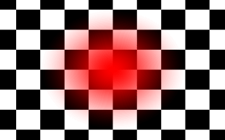
Using a glowing halo gives the expected result.

Even though the red color of the high density areas is not very visible because the green colored, lower density areas lying in front absorb most of the red light, we don't get yellow color where we would have expected a red one.

Due to its similarity with the emitting halo we have to make some experiments with this halo type. We just have to keep all those things we learned in the previous sections in mind to get some satisfying results.


Section 4.8.5.4
The Attenuating Halo

Another simple halo type is the attenuating halo that only absorbs light. It doesn't radiate on its own.

A great difference between the attenuating halo and the other halo types is that the color of the attenuating halo is calculated from the halo's color map using the total particle density along a given ray. The other types calculated a (weighted) average of the colors calculated from the density at each sample.


Section 4.8.5.4.1
Making a Cloud

Attenuating halos are ideal to create clouds and smoke. In the following examples we will try to make a neat little cloud. We start again by using a unit-sized sphere that is filled with a basic attenuating halo (halo21.pov).

camera { location <0, 0, -2.5> look_at <0, 0, 0> } light_source { <10, 10, -10> color rgb 1 shadowless } plane { z, 2 pigment { checker color rgb 0, color rgb 1 } finish { ambient 1 diffuse 0 } scale 0.5 hollow } sphere { 0, 1 pigment { color rgbt <1, 1, 1, 1> } halo { attenuating spherical_mapping linear color_map { [ 0 color rgbt <1, 0, 0, 1> ] [ 1 color rgbt <1, 0, 0, 0> ] } samples 10 } hollow }

Even though clouds normally are not red but white or gray, we use the red color to make it more visible against the black/white checkerboard background.

The color of an attenuating halo is calculated from the total accumulated density after a ray has marched through the complete particle field. This has to be kept in mind when creating the color map. We want the areas of the cloud with a low density to have a high translucency so we use a color of rgbt<1,0,0,1> and we want the high density areas to be opaque so we choose a color of rgbt<1,0,0,0>.


The basic attenuating halo used to create a cloud.


Section 4.8.5.4.2
Scaling the Halo Container

The cloud we have created so far doesn't look very realistic. It's just a red, partially translucent ball. In order to get a better result we use some of the methods we have already learned in the sections about emitting halos above. We add some turbulence to get a more realistic shape, we scale the halo to avoid the container object's surface to become visible and we decrease the translucency of the areas with a high particle density.

Another idea is to scale the container object to get an ellipsoid shape that can be used to model a cloud pretty good. This is done by the scale <1.5, 0.75, 1> command at the end of the sphere. It scales both, the sphere and the halo inside.

sphere { 0, 1 pigment { color rgbt <1, 1, 1, 1> } halo { attenuating spherical_mapping linear turbulence 1 color_map { [ 0 color rgbt <1, 0, 0, 1> ] [ 1 color rgbt <1, 0, 0, -1> ] } samples 10 scale 0.75 } hollow scale <1.5, 0.75, 1> }

Looking at the results of halo22.pov we see that this looks more like a real cloud (besides the color).


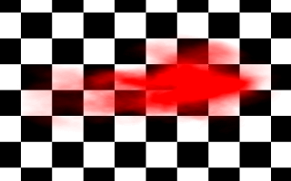
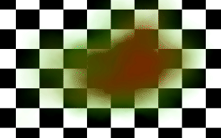
Scaling the halo container and adding some turbulence gives a better result.


Section 4.8.5.4.3
Adding Additional Halos

Another trick to get some more realism is to use multiple halos. If we look at cumulus clouds e. g. we notice that they often extend at the top while they are quite flat at the bottom.

We want to model this appearance by adding two additional halos to our current container object (see section "Multiple Halos" for more details). This is done in the following way:

sphere { 0, 1.5 pigment { color rgbt <1, 1, 1, 1> } halo { attenuating spherical_mapping linear turbulence 1 color_map { [ 0 color rgbt <1, 0, 0, 1> ] [ 1 color rgbt <1, 0, 0, -1> ] } samples 10 scale <0.75, 0.5, 1> translate <-0.4, 0, 0> } halo { attenuating spherical_mapping linear turbulence 1 color_map { [ 0 color rgbt <1, 0, 0, 1> ] [ 1 color rgbt <1, 0, 0, -1> ] } samples 10 scale <0.75, 0.5, 1> translate <0.4, 0, 0> } halo { attenuating spherical_mapping linear turbulence 1 color_map { [ 0 color rgbt <1, 0, 0, 1> ] [ 1 color rgbt <1, 0, 0, -1> ] } samples 10 scale 0.5 translate <0, 0.2, 0> } hollow }

The three halos used differ only in their location, i. e. in the translation vector we have used. The first two halos are used to form the base of the cloud while the last sits on top of the others. The sphere has a different radius than the previous ones because more space is needed for all three halos.

The result of halo23.pov somewhat looks like a cloud, even though it may need some work.


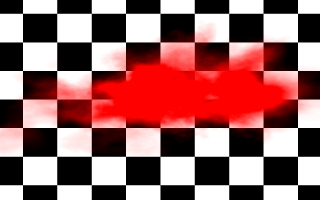
Using multiple halos pretty much improves our cloud.


Section 4.8.5.5
The Dust Halo

The dust halo is a very complex halo type. It allows us to see the interaction of light coming from a light source with the particles in the halo. These particles absorb light in the same way as the attenuating halo. In addition they scatter the incoming light. This makes beams of light and shadows cast by objects onto the halo become visible.

Section 4.8.5.5.1
Starting With an Object Lit by a Spotlight

We start with a box shaped object that is lit by a spotlight. We don't use any halo at this moment because we want to see if the object is completely lit by the light (halo31.pov).

camera { location <0, 0, -2.5> look_at <0, 0, 0> } background { color rgb <0.2, 0.4, 0.8> } light_source { <2.5, 2.5, -2.5> colour rgb <1, 1, 1> spotlight point_at <0, 0, 0> radius 12 falloff 15 tightness 1 } difference { box { -1, 1 } box { <-1.1, -0.8, -0.8>, <1.1, 0.8, 0.8> } box { <-0.8, -1.1, -0.8>, <0.8, 1.1, 0.8> } box { <-0.8, -0.8, -1.1>, <0.8, 0.8, 1.1> } pigment { color rgb <1, 0.2, 0.2> } scale 0.5 rotate 45*y rotate 45*x }


The object we want to use.

As we see the whole object is lit by the light source. Now we can start to add some dust.


Section 4.8.5.5.2
Adding Some Dust

We use a box to contain the dust halo. Since we use a constant density function it doesn't matter what kind of density mapping we use. The density has the value specified by the max_value keyword everywhere inside the halo (the default value is one). The isotropic scattering is selected with dust_type .

box { -1, 1 pigment { colour rgbt <1, 1, 1, 1> } halo { dust dust_type 1 box_mapping constant colour_map { [ 0 color rgbt <1, 1, 1, 1> ] [ 1 color rgbt <1, 1, 1, 0> ] } samples 10 } hollow scale 5 }


This dust is too thick.

The result of halo32.pov is too bright. The dust is too thick and we can only see some parts of the object and no background.


Section 4.8.5.5.3
Decreasing the Dust Density

The density inside the halo has the constant value one. This means that only the color map entry at position one is used to determine the density and color of the dust.

We use a transmittance value of 0.7 to get a much thinner dust.

box { -1, 1 pigment { colour rgbt <1, 1, 1, 1> } halo { dust dust_type 1 box_mapping constant colour_map { [ 0 color rgbt <1, 1, 1, 1.0> ] [ 1 color rgbt <1, 1, 1, 0.7> ] } samples 10 } hollow scale 5 }


A thinner dust looks much better.

Beside the ugly aliasing artifacts the image looks much better. We can see the whole object and even the background is slightly visible (halo33.pov).


Next Section
Table Of Contents