Section 7.6.4.3
Halo Type

The type of the halo is defined by one of the following mutually exclusive keywords (if more than one is specified the last will be used). The default is attenuating.

halo { attenuating | emitting | glowing | dust }

The halo type determines how the light will interact with the particles inside the container object. There are two basic categories of light interaction: self-illuminated and illuminated. The first type includes the attenuating, emitting and glowing effects while the dust effect is of the second type.

The four types will be covered in detail in the next sections.


Section 7.6.4.3.1
Attenuating

The attenuating halo that only absorbs light passing through it is rendered by accumulating the particle density along a ray. The total halo color is determined from the total, accumulated density and the specified color map (see section "Halo Color Map" for details about the color map). The background light, i. e. the light passing through the halo, is attenuated by the total density and added to the total halo color to get the final color of the halo.

This model is suited to render particle distributions with a high albedo because the final color does not depend on the transparency of single volume elements but only on the total transparency along the ray. The albedo of a particle is given by the amount of light scattered by this particle in all directions in relation to the amount of incoming light. If the particle doesn't absorb any light the albedo is one.

Clouds and steams are two of the effects that can be rendered quite realistic by adding enough turbulence.


Section 7.6.4.3.2
Dust

The dust halo consists of particles that do not emit any light. They only reflect and absorb incoming light. Its syntax is:

halo { dust [ dust_type DUST_TYPE ] [ eccentricity ECCENTRICITY ] }

As the ray marches through the dust all light coming from any light sources is accumulated and scattered according to the dust type and the current dust density. Since this light accumulation includes a test for occlusion, other objects may cast shadows into the dust.

The same scattering types that are used with the atmosphere in section "Atmosphere" can be used with the dust (the default type is isotropic scattering). They are:

#declare ISOTROPIC_SCATTERING = 1 #declare MIE_HAZY_SCATTERING = 2 #declare MIE_MURKY_SCATTERING = 3 #declare RAYLEIGH_SCATTERING = 4 #declare HENYEY_GREENSTEIN_SCATTERING = 5

The Henyey-Greenstein function needs the additional parameter eccentricity that is described in the section about atmosphere. This keyword only applies to dust type 5, the Henyey-Greenstein scattering.


Section 7.6.4.3.3
Emitting

Emitting halos only emit light. Every particle is a small light source that emits some light. This light is not attenuated by the other particles because they are assumed to be very small.

As the ray travels through the density field of an emitting halo the color of the particles in each volume element and their differential transparency is determined from the color map. These intensities are accumulated to get the total color of the density field. This total intensity is added to the light passing through the halo. The background light is attenuated by the total density of the halo.

Since the emitted light is not attenuated it can be used to model effects like fire, explosions, light beams, etc. By choosing a well suited color map those effects can be rendered with a high degree of realism.

Fire is best modeled using planar mapping. Spherical mapping and high turbulence values can be used to create explosions (it's best to use a periodic color map and frequencies larger than one).

Emitting halos do not cast any light on other objects like light sources do, even though they are made up of small, light-emitting particles. In order to make them actually emit light hundreds or thousands of small light sources would have to be used. This would slow down tracing by a degree that would make it useless.


Section 7.6.4.3.4
Glowing

The glowing halo is similar to the emitting halo. The difference is that the light emitted by the particles is attenuated by the other particles. This can be seen as a combination of the attenuating and the emitting model.

Section 7.6.4.4
Density Mapping

The density mapping is used to map points in space onto a linear, one-dimensional interval between 0.0 and 1.0, thus describing the appearance of the three-dimensional particle distribution. The different mapping types are specified by:

halo { planar_mapping | spherical_mapping | cylindrical_mapping | box_mapping }

The default mapping type is planar mapping.

Since the mapping takes place in relation to the origin of the world coordinate system the following rule must always be kept in mind: Halo container objects ought to be unit sized objects centered at the origin. They can be transformed later to suit the individuals needs.

The different mapping types are explained in more detail in the following sections.


Section 7.6.4.4.1
Box Mapping

The box mapping can be used to create a box-shaped particle distribution. The mapping is calculated by getting the maximum of the absolute values of each coordinate as given by the formula:

r(x, y, z) = max(abs(x), abs(y), abs(z))

Values larger than one are clipped to one.


Section 7.6.4.4.2
Cylindrical Mapping

The distance r(x,y,z) from the y-axis given by

r(x, y, z) = sqrt(x*x + z*z)

is used to get the interval values. Values larger than one are clipped to one.


Section 7.6.4.4.3
Planar Mapping

The distance r(x,y,z) from the x-z-plane given by

r(x, y, z) = abs(y)

is used to get the interval values. Values larger than one are clipped to one.


Section 7.6.4.4.4
Spherical Mapping

The distance r(x,y,z) from the origin given by

r(x, y, z) = sqrt(x*x + y*y + z*z)

is used to get the interval values. Values larger than one are clipped to one.


Section 7.6.4.5
Density Function

The density function determines how the actual density values are calculated from the linear, one-dimensional interval that resulted from the density mapping.

The density function is specified by the following keywords:

halo { [ constant | linear | cubic | poly ] [ max_value MAX_VALUE ] [ exponent EXPONENT ] }

The exponent keyword is only used together with the poly density function.

The individual functions f(r) are described in the following sections. They all map the value r(x,y,z) calculated by the density mapping onto a suitable density range between 0 and MAX_VALUE (specified with the keyword max_value).


Section 7.6.4.5.1
Constant

The constant function gives the constant value MAX_VALUE regardless of the interval value and the type of density mapping. It is calculated by the trivial formula f(r) = MAX_VALUE.


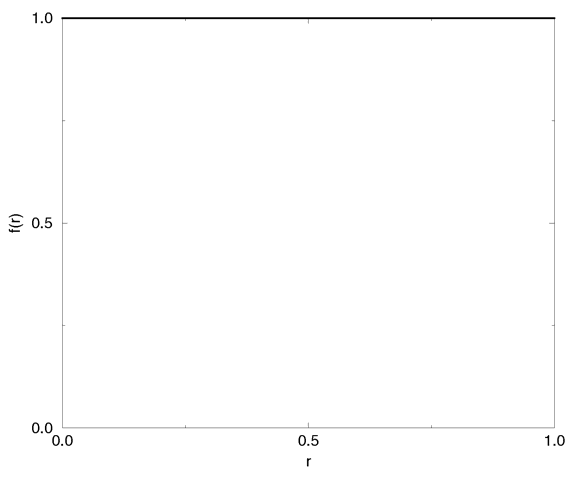
The constant density function.

The constant density function can be used to create a constant particle distribution that is only constrained by the container object.


Section 7.6.4.5.2
Linear

A linear falloff from MAX_VALUE at r=0 to zero at r=1 is created with the linear density function. It is given by:

f(r) = MAX_VALUE * (1 - r)


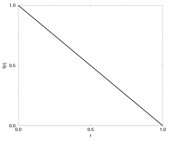
The linear density function.


Section 7.6.4.5.3
Cubic

The cubic function gives a smooth blend between the maximum value MAX_VALUE at r=0 and 0 at r=1. It is given by:

f(r) = MAX_VALUE * (2 * r - 3) * r * r + 1


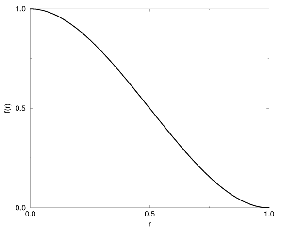
The cubic density function.

This is actually a cubic spline.


Section 7.6.4.5.4
Poly

A polynomial function can be used to get a large variety of density functions. All have the maximum value MAX_VALUE at r=0 and the minimum value 0 at r=1. It is given by:

f(r) = MAX_VALUE * (1 - r) ^ EXPONENT


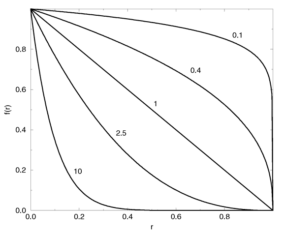
The polynomial density function for different exponent values.

The exponent is given by the exponent keyword. In case of EXPONENT=0 you'll get a linear falloff.


Section 7.6.4.6
Halo Color Map

The density f(r), which ranges from 0 to MAX_VALUE, is mapped onto the color map to get the color and differential translucency for each volume element as the ray marches through the density field (the final color of attenuating halos is calculated from the total density; see section "Halo Mapping" and section "Attenuating"). The differential translucency determines for each value of f(r) how much the total opacity has to be increased (or decreased).

The color map is specified by:

halo { [ colour_map COLOUR_MAP ] }

The differential translucency is stored in the transmittance channel of the map's color entries. A simple example is given by

colour_map { [0 rgbt<1, 1, 1, 1>] [1 rgbt<1, 1, 1, 0>] }

In this example areas with a low density (small f(r)) will be translucent (large differential translucency of 1=100%) and areas with a high density (large f(r)) will be opaque (small differential translucency of 0=0%). You should note that negative transmittance values can be used to create very dense fields.

In the case of the dust halo the filter channels of the colors in the color map are used to specify the amount of light that will be filtered by the corresponding color map entry. For all other halo types the filter value is ignored.

There is no default color map.


Next Section
Table Of Contents